LFC™_3B Pilot Operated Pressure Regulating Valve
 OVERVIEW
A pressure regulating valve is designed to maintain a desired downstream pressure irrespective of the flow requirement. The LFC™_3B variable ratio pressure regulating valve has been developed to present a robust, simple and cost-effective low pressure (up to 2.5 MPa / 363 psi) solution to fluid handling issues in any industrial sector.
FEATURES
- Reduced cavitation
- Low noise levels
- Low vibration
- One moving part
- Long lasting
SIMPLICITY
The LFC™_3B Pilot operated pressure regulating valve is designed to minimize wearing parts and in effect only has one moving part called the plug assembly. The plug assembly is a piston that is engineered to be unbalanced. The unbalanced plug assembly combined with a pilot are designed to use inline fluid pressure to create specific conditions in the system.
Its equipped with a 3-way pilot that controls the downstream pressure. A needle valve allows upstream pressure to flow into the valve top closing compartment at a controlled flow rate.
The pilot releases pressure from the valve to compartment at an adjustable rate. By adjusting the adjustment screw, the downstream control pressure can be adjusted to the desired downstream pressure. The pilot will ensure that the downstream pressure will remain stable, even if the upstream pressure changes with demand changes.
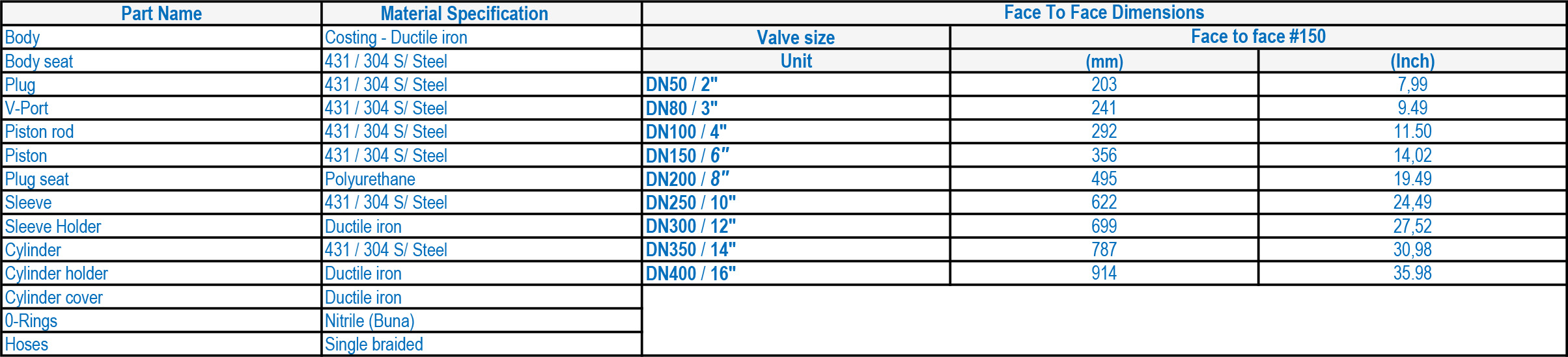
MATERIALS OF CONSTRUCTION & DIMENSIONS
LOW MAINTENANCE REQUIREMENT
All the moving parts of LFC™_3B surge relief valve are manufactured from stainless steel which increases reliability and durability. The LFC™_3B requires minimal maintenance, the majority of which, can be conducted with the valve remaining in situ.
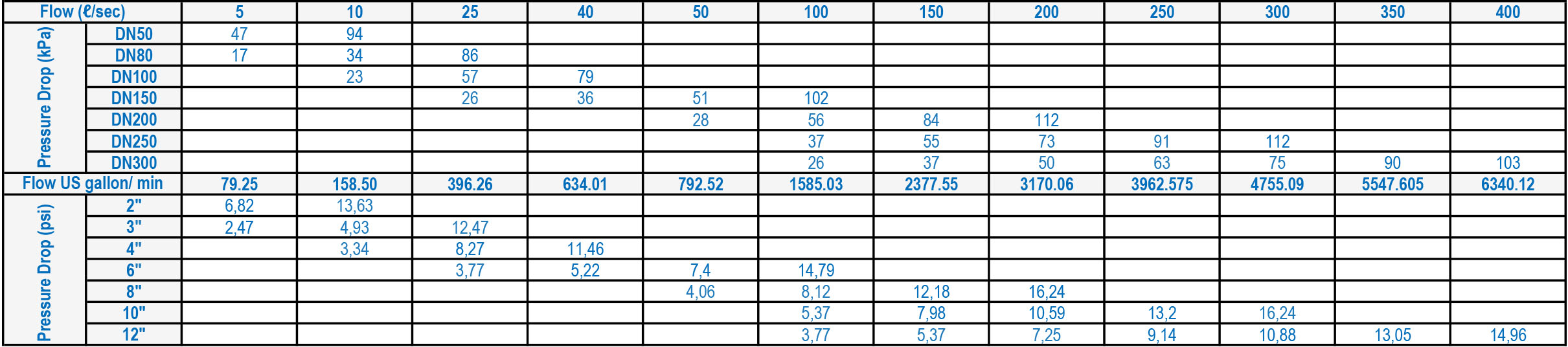
FLOW RATES
PLUG ASSEMBLY, V-PORT AND DEALING WITH CAVITATION
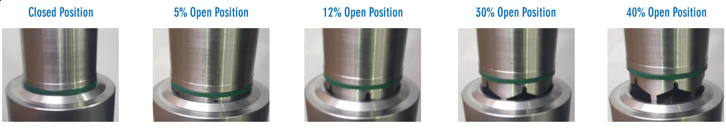
As displayed, the LFC™_3B pressure regulating valve plug assembly and movements.
Closed Position: Shows the plug assembly on the body seat in a fully closed valve position.
5% Open Position: Shows the plug assemble in a 5% open position. It can clearly be seen that only the top of the V-Port opens up and creates a flow path. This reduces cavitation and helps with fine control at low flow conditions.
12% Open Position: Shows the plug assembly in the 12% open position. Now it can be observed how the V-Port moved away from the seat and the openings are increasing proportionally. At this point the top of the V-Ports are now being exposed to the flow path.
30% Open Position: Shows the plug assembly in the 30% opened position. Now it can clearly be seen that the full V-Port is creating a larger orifice in the flow path. Up to this point, cavitation needs to be dealt with to increase the life expectancy of the valve. The V-port trim ensures that the seating elements are further apart from each other during low flow allowing the cavitation to take place on noncritical components of the valve.
40% Open Position: Shows the plug assembly in the 40% open position. Now it can clearly be seen that the V-Port is completely away from the seat and the flow path is now relatively large. At this point the flow is approaching its medium demand flow rate and the V-Port has little to no function.
ROBUST, RELIABLE AND EFFICIENT
Due to the minimal number of moving parts to effect the fluid control, the number of potential failures are minimized. The valve can only fail for the following reasons:
1. Lack of maintenance: If filters are utilized in the control system, regular cleaning of the filters are required to prevent the valve operation from slowing down and eventu ally creating a possible hydraulic locking of the valve. This process depends on the condition of the service water being used. The dirtier the water, the shorter the filter maintenance intervals will need to be. A valve seal replacement program should be employed to ensure that the valves plug seals are replaced in accordance with manu facturer 's recommendations. As these seals are largely protected the intervals for maintenance on these items can usually be done in terms of years. If these seals fail, the valve will start to bypass pressure from the Pu to the air vent chamber. Valves are equipped with tell-tale breather holes which will immediately indicate seal failure .
2. Mechanical fouling: Should a large object be introduced into the service water piping and reach the valve inlet, such object could create a mechanical jam and prevent the plug from operating.
3. Overriding of the control system: As the valve is hydraulically actuated and controlled, if the control system is isolated from the service water by way of isolation valves in the control system, the valve will be hydraulically locked in position and will be unable to adjust to the inline condition changes .
4. Mechanical failure of the main seating arrangement: In time, the seating arrangement will experience conditions of high velocity across the seating surface during low flow conditions. The high velocity will eventually cause wear on the seating surface and on the plug seating surface. If the valves starts to bypass across its seat, the down stream pressure could increase to the point where the pressure relief valve is activated during low flow conditions.
All of these conditions are easily avoidable and rectifiable through regular maintenance programs and service water quality control and condition monitoring.
DESIGN AND MANUFACTURING STANDARDS
The LFC™_3B has been designed in accordance with various international standards as set out below:
ASME Boilers and pressure vessels design code
ANSI Bl6.10
ANSI Bl6.3
ANSI B16.34
ANSI B16.37
ANSI Bl6.5
ANSI N278.1
Available sizes: DN50 / 2" to DN400 / 16"
Face to face dimensions to ANSI Bl6.10
Pressure rating: up to 2,5 MPa / 363 psi
Available end connections: ANSI Bl 6.5, BS4504, BS10, AS/NZS 4331.1 (ISO 7005-1) DIN, All makes of grooved or ring joint couplings, and other as per client’s requirement.
DOWNLOADS